Steel halls and structures
How loads travel through a steel building from roof to foundations
In brief
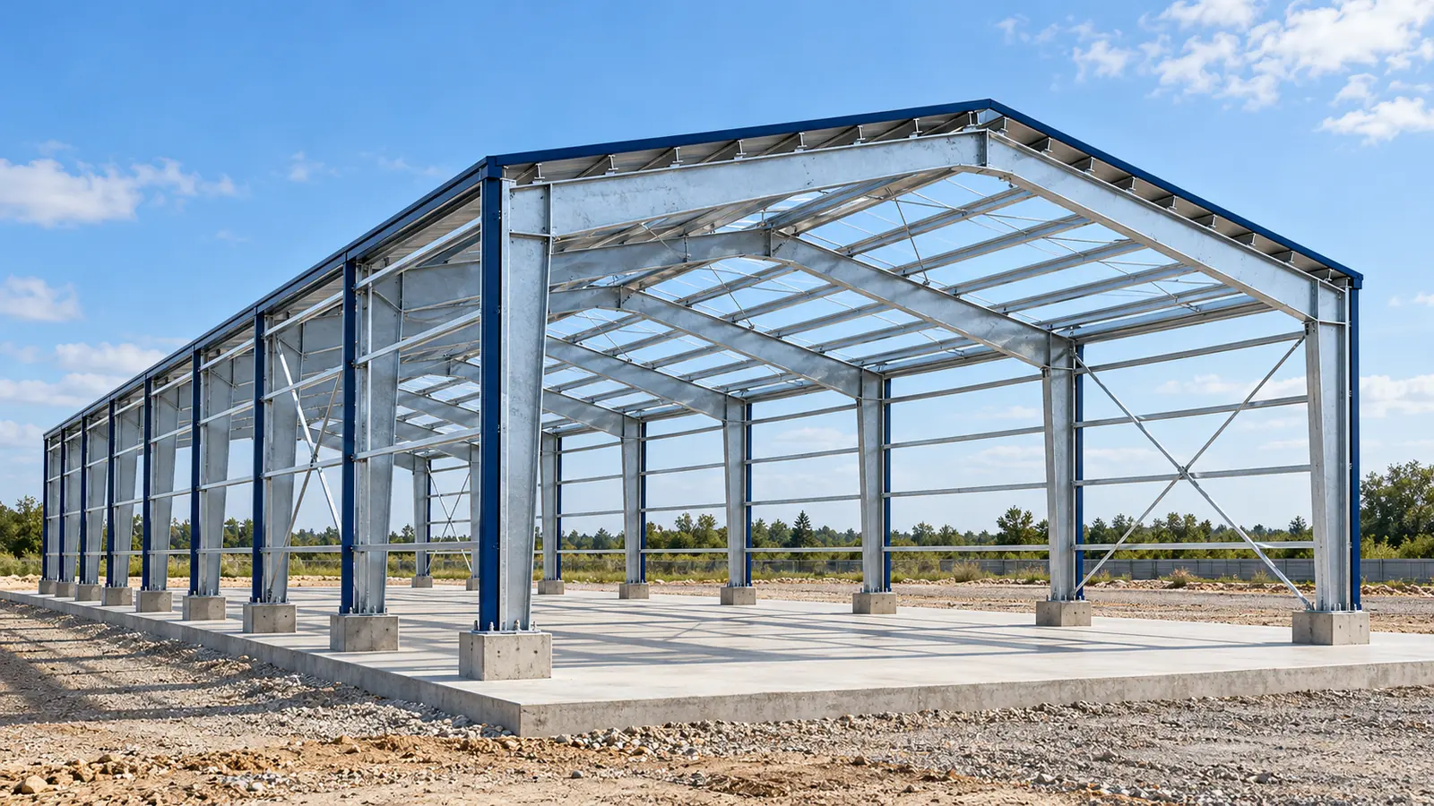
In a photo of a steel hall, the large columns and the roof are the easiest things to notice. Less visible are the elements that tie them together into a single three-dimensional system. It is their interaction that allows loads to be transferred to the ground. To understand the structure, you do not need to calculate the profiles yourself. It is enough to know the path the forces take and why breaking that path can change how the building behaves. A steel hall is acted upon by its own weight, the envelope, snow and wind. Loads related to use and equipment are added. Some forces are vertical, some horizontal. Wind can both press a section of the enclosure against its supports and pull it away from them. That is why the design is not based solely on assessing the weight resting on the roof.
It all starts with the load
The steel structure is verified for the relevant load combinations. Not only load-bearing capacity matters, but also deflections and displacements. Excessive deformation can impede the operation of doors or damage the associated cladding. A correct design therefore covers the behaviour of the whole, not merely the condition that an individual profile does not fracture.
Panels transfer forces to the supports
In a steel hall clad with sandwich panels, the panel has a defined span and fixing method. Loads are transferred through supports and fasteners to the further elements. The distance between supports cannot be increased arbitrarily simply because the panel appears rigid. Its type, thickness, arrangement and operating conditions all matter.
Fixings belong to the same load path. A fastener selected for the wrong substrate or placed in the wrong position can reduce the capacity of the solution. In corner and edge zones, wind conditions differ from those at the centre of the enclosure. Steel structures and the cladding must therefore be designed together, taking all connections into account.
Purlins and side rails connect successive frames
Purlins support the roof covering and transfer loads to the rafters of the main frames. Wall rails perform a similar function on the façade. In many steel halls they are made from thin-walled cold-formed profiles. Their low weight does not mean low responsibility. They act as load-bearing elements and may participate in stabilising part of the frame.
The method of fixing the purlins and their support are significant for the entire system. It must not be assumed that the cladding will always provide the required bracing. Such interaction must be envisaged and documented. Likewise, replacing a panel or removing a section of covering can change the support conditions of the steel structure elements.
The frame works in its own plane
A portal frame consists of columns and roof rafters connected at appropriately rigid joints. This enables it to carry vertical and horizontal loads in its plane. It is not true that every steel hall frame without diagonal bracing in the nave must be unstable. What matters is the adopted structural scheme and the stiffness of the connections.
However, the steel structure also needs stabilisation in the longitudinal direction of the building. This is provided by designed bracing or other suitable systems. The slender members in the wall and roof are not merely a tidying addition. They connect the frames and help transfer forces to locations where they can be safely passed to the foundations.

From column to substrate
Forces from the column pass through the base plate and the connection to the foundation. Depending on the design, various support solutions are used. Anchor bolts, base plate, grout and concrete form a specific detail. It cannot be replaced with any set of similar parts. A steel hall requires execution to be consistent with the assumed support behaviour.
The foundation transfers the actions to the ground. Its selection depends on the structural reactions and the ground conditions. The floor slab has a different primary function and does not automatically replace the column foundation. Even a light steel hall can transfer significant horizontal or uplift forces. A low mass does not exempt you from checking the foundation.
Changing one element affects the system
A new gate, roof-mounted equipment or a removed brace can change the load path. This applies both to individual structures and to modular steel structures. Before making a change, establish the function of the element and verify the replacement solution. Assessing it solely by its size or visible load can be misleading.
In the documentation for the steel hall, keep the drawings of the bracing, connections and supports. Report additional installations together with their mass and fixing location. Do not treat a free hole in the profile as permission to suspend equipment. Steel structures can look similar while having a different structural behaviour. Begin the assessment of a modification with data on the as-built condition.
Check that the building envelope is consistent with the requirements assumed in the design of the supports. Do not remove bracing without a design. The fixing also transfers load. The support must correspond to the calculations. A connection is part of the structure, even if it costs less than the profiles it connects. Understanding the load path makes it easier to ask the right questions during acceptance of the building.
Every element should have a known place and function within the overall scheme.
7 branches. Materials closer to your project.