Profiles and steel structures
Hole patterns in cold-formed steel sections: preparing production drawings
In brief
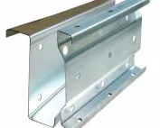
Factory-made holes can make installation considerably easier. The prerequisite is correct documentation, because an error in the drawing will be reproduced just as faithfully as a correct detail. When requesting punched cold-formed profiles, it is not enough to specify the diameter and spacing. A dimension datum, the orientation of the cross-section and an unambiguous version of the component are also required. Data prepared in this way reduce the number of queries and rework. The cross-section drawing describes the shape and thickness of the profile. The longitudinal view shows its length and the arrangement of the holes. The two pieces of information should be linked. A flat-strip view alone may not make it clear which flange the hole is to be in. More complex geometry requires additional views.
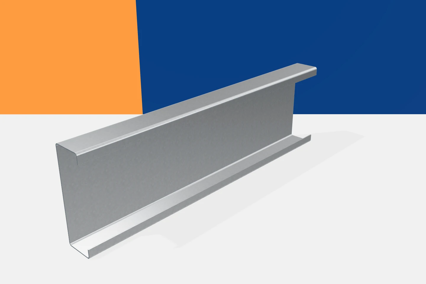
Separate the cross-section from the view of the whole element
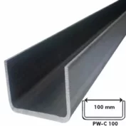
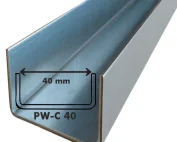
This applies in particular to Z-sections and sigma profiles. Channels also require the opening side to be specified. In omega profiles, the holes may be located in different parts of the cross-section depending on the design. Rather than relying on the fabricator’s interpretation, it is worth marking the position directly on the relevant view.
Choose one dimension datum
The hole position must be measured from a specified end and a specified surface. Mixing datum references without explanation should be avoided. Dimensioning from the left on one drawing and from the right on another easily leads to error, particularly when the component has several similar variants.
It is worth stating the full length of the segment and checking dimensional consistency. The sum of the segments should match the intended geometry. If the documentation uses coordinates, the same units must be retained. Dimensions should not be left to be read from the print scale, as the file may be displayed or printed at a different size.
The viewing side must be clear
For an asymmetric profile, a mirror-reversed drawing describes a different part. The position of the flanges and the direction of the component must therefore be specified. Linking to the axis number or installation location is helpful. The designation should appear both in the schedule and on the fabrication drawing.
Different components should not be given the same number merely because they have an identical length. The hole pattern may determine their purpose. The distinction between left-hand and right-hand versions must be established consistently. This will also facilitate packing, receiving and issuing parts on site.
The hole shape results from the detail
Round holes, slotted holes and other cut-outs serve different functions. If the design allows for adjustment, its direction and range must be specified. A slotted hole should not be created only after discovering that the bolt does not fit. It is part of the connection solution and requires proper verification.
Edge, end and bend-zone distances matter. They should not be set solely according to the space available on the drawing. Holes affect the cross-section and the behaviour of the connection. Their layout should come from approved documentation, consistent with the material and the anticipated loads.

Agree feasibility before approving the batch
The hole-making options depend on the process, tooling and profile geometry. An unusual detail may require a different sequence of operations or additional processing. It is worth clarifying this at the enquiry stage. The supplier should confirm compliance with the requirements rather than replace them with its own solution without agreement.
Tolerances must be related to the actual assembly requirements. An overly general instruction such as “exactly” settles nothing. Conversely, requirements unrelated to function may make production unnecessarily difficult. The correct level of accuracy should follow from the documentation and the mating components.
Drawing versioning protects against mixed-up changes
After a hole-layout correction, the documentation must be given a new version designation. The scope of the change must be stated and the version in force confirmed. Simply sending another attachment with the same name may be insufficient, especially when the enquiry, quote and production take place at different times.
If some of the material has already been produced, the further course of action must be agreed. It cannot be assumed that a correction in the file automatically changes finished parts. The possibility of reworking or the need for new components must be assessed. This also applies to galvanised profiles, where additional processing affects the surface condition.
A three-dimensional model file can help in preparing production, but its consistency with the drawing must be established. If the two documents contain different values, clarification is needed before the part is made. There should not be two equally valid, contradictory descriptions. The order should state the format and version of the data adopted for execution.
Inspection should cover more than the first hole
At acceptance, it is worth comparing the length, orientation and several characteristic positions. It should be checked whether the part numbers correspond to the drawings. The quantity of each variant is also important. A matching first hole does not prove that the entire hole pattern has been made correctly.
Well-prepared cold-formed profiles make it possible to reduce drilling on site. Z-sections, channels, sigma and omega profiles then become repeatable parts of the set. The greatest benefit is predictability of assembly. This is achieved through precise agreements before production, not by increasing the number of holes just in case.
7 branches. Materials closer to your project.