Profiles and steel structures
Omega profiles to size: specifying the cross-section clearly
In brief
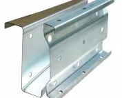
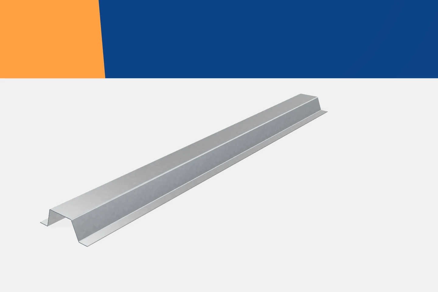
With omegas, misunderstandings are particularly easy. Two parts can have the same height and still fit the substructure completely differently. The flange widths, the central web, the bend angles and the sheet thickness all matter. Omega profiles must therefore be described with a full drawing. The general name of the shape helps to identify the family, but it is not enough to start production. It is worth establishing which part of the profile will be fixed to the substrate and which will support the next element. Omegas can have different orientations depending on the solution. The drawing should show the actual arrangement once assembled. This allows assessment of access to the fasteners and the space needed around the part.
Start with the surfaces that are to come into contact
It should not be assumed that all cold-formed hat-shaped profiles are used identically. A façade subframe may have different requirements from an equipment support element. If the profile is to carry loads, its selection requires appropriate assessment. A convenient installation shape is not on its own confirmation of load-bearing capacity.
Dimension the entire geometry
The height, the width of the central web and both flanges are required. The thickness, angles and bend radii must also be specified, or a standard cross-section clearly indicated. If the flanges have different dimensions, each must be described separately. The drawing should clarify whether the values given are external.
It is not advisable to determine the developed width yourself by simply adding the visible sections. Bends require the correct allowances and material geometry to be taken into account. The plant should prepare the process for the approved shape. The buyer primarily specifies the required result and the surfaces relevant for installation.
Thickness must be linked to function
Choosing thin sheet solely for a lower price can change the behaviour of the subframe. Conversely, increasing the thickness does not always solve a problem of incorrect fixing. The profile and the connections must form a compatible system. The loads, the support spacing and the way forces are transferred all matter.
Permissible displacements are also important. The cladding subframe should maintain the required service conditions. It is not enough to check that the element will not fail. A subframe that is too flexible can hinder the correct functioning of the fixed components. The thickness should therefore come from selection, not from an intuitive comparison of samples.
Holes facilitate installation if they are well described
For serial elements, factory perforation should be considered. The position, diameter or shape of the holes and their number must be specified. The measuring datum must be indicated. For long sections, it is also advisable to establish part numbering and the direction in which the drawing is to be read.
A slotted hole must not arise by chance through enlarging a round one. If it is to allow adjustment, it should be part of a designed detail. The range of movement and the method of tightening the connection are significant. Any additional processing changes the description of the component, so it should be included in the production documentation.

Coating and service conditions are equally important
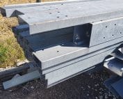
Galvanised omega profiles may work in a sheltered zone or in a substructure exposed to moisture. The choice of protection must take actual exposure into account. The type of coating and the material of the fasteners must be specified. The compatibility of materials in direct contact must also be checked.
It is worth planning access for later inspection or a method of assessment before the framework is covered. Unforeseen gaps that trap water can worsen the working conditions. A greater amount of zinc alone does not correct every detail error. Geometry, surface protection and moisture drainage should be considered together.
Can a different profile be used?
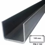
C-sections, Z-sections and sigma sections have a different profile shape from omegas. They may be useful in many substructures, but they do not automatically replace them. A change of shape affects the fastening surface and the position of the load. It sometimes also requires different fasteners or intermediate components.
An alternative should be considered before production, on the basis of the same task. It may turn out that a standard profile simplifies the order. A precisely specified non-standard section may also be needed. The decision should follow from geometry and calculations, not merely from the availability of the first component found.
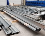
In the enquiry it is also worth indicating how long sections will be used. If they will be divided after delivery, the cutting plan and the identification of shorter parts must be taken into account. Sometimes exact lengths straight from the works simplify the whole process. However, the choice should take into account both the cost of processing and the surface requirements after the edges have been formed.
Approve the pattern and scope of supply
Before confirming the order, the drawing, lengths and number of pieces must be checked. It is worth agreeing the tolerances relevant to installation and the method of inspection. For a larger batch, an approved sample or the first component may be helpful. It does not replace the documentation, but it allows practical fit to be checked.
Finished omegas should be marked so that their purpose can be recognised. This applies especially to similar parts that differ in their holes. Well-described cold-formed profiles arrive at installation as a repeatable set. This makes use of the advantage of production to size without transferring missing decisions to the site.
7 branches. Materials closer to your project.