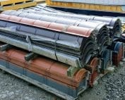
Sheet metal flashings
Specifying left- and right-hand verge flashings on a roof drawing
In brief
The term left verge flashing is often ambiguous. It depends on which side we view the roof from and how we read the cross-section. When ordering, it is better to rely on a sketch than on the name alone. Verge flashings should be assigned to specific edges and their visible side marked. This is particularly useful for asymmetric elements, multiple roof slopes and different wall heights. On the building plan, it is worth marking the entrance side or another easily recognisable orientation. Then the individual gables and edges are marked. The person preparing the flashings should read the sketch in the same way as the installer. This helps avoid reversing the order.
Choose one viewing direction
Verge flashings are best described by their location symbol and cross-section. The name left or right can remain as supplementary information. It should not be the only way of distinguishing the elements. If a finished part can genuinely be used on both sides, it is worth confirming this on the drawing rather than assuming it in advance.
Measure the edge along its actual course
The length of the verge flashing corresponds to the edge of the roof slope, and not always to the dimension visible on the building plan. The roof pitch and its terminations must be taken into account. An initial reading from the design is worth comparing with the finished covering. The measurement should be taken by an installer with safe access to this area.
Sections separated by a step or another detail are recorded separately. They should not be combined into a single overall dimension. A short section at the lower roof may require a different cross-section. In the order, both the total quantity of material and the breakdown into specific elements are therefore important.
Determine both arms and the bends
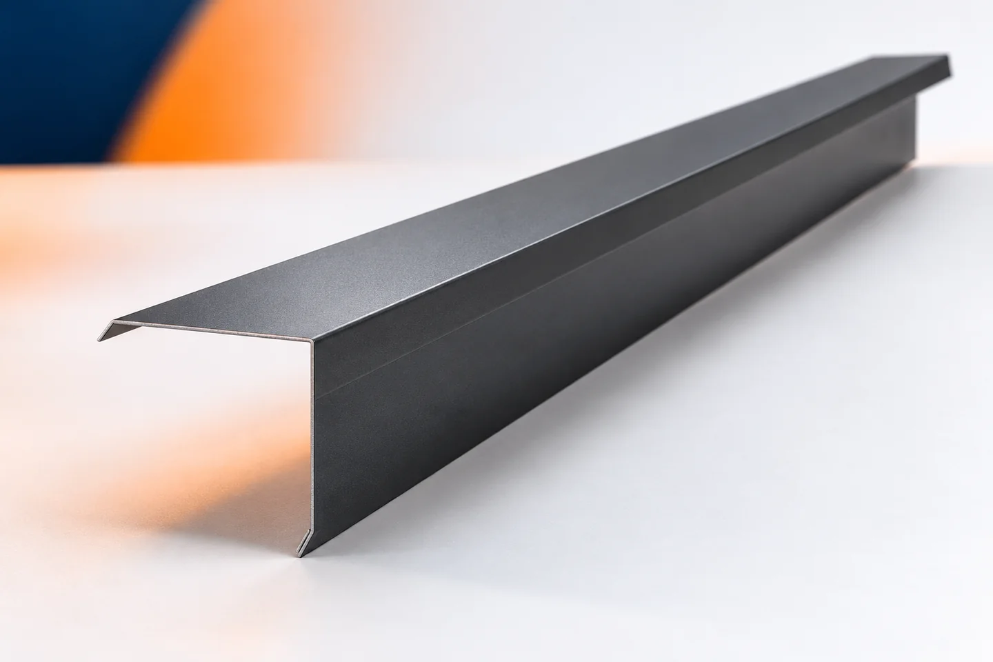
The visible side part of the verge flashing is only a fragment of the cross-section. The upper arm works together with the covering, and the edge folds have their own significance. All dimensions should appear on the sketch. It is not enough to state the height of the board or the thickness of the insulated sandwich panel.
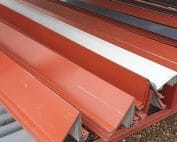
The position of the flashing relative to the roof profile must also be determined. A different arrangement may be needed with a projecting eaves, and another at an edge without an overhang. The catalogue shape should be assessed for the specific situation. Verge flashings that look similar in a photograph may sit differently against the covering.
Mark where the colour should be
In asymmetric flashings, the coated side determines how the component can be fitted. Turning the finished part over does not always resolve the mistake. On the drawing, it is worth clearly indicating the surface visible after installation. Such a record is clearer than a verbal description passed between several people.
Coated steel sheets are also selected according to the type of finish. The same colour code can occur in different surface versions. For galvanised and aluzinc sheets, the required material must also be specified. The absence of a colour does not exempt you from stating the protection specification and thickness.

Include the connections and the joint at the ridge
If a verge flashing consists of several sections, part of the length will be used for joining them. The number of pieces must be calculated according to the correct detail. This matter should not be left to be resolved after unloading. It is also worth allowing for possible cutting of the last element.
At the top, the verge flashings connect with ridge caps. At the bottom, they meet the gutter aprons or other eaves components. These places must be matched as a complete set. A missing short end flashing can delay installation even if all the long sections have been delivered.
Separate standard elements from those tailored to the building
Not every dimensional change requires inventing an entirely new profile. It is worth first checking catalogue solutions and their range of application. If they do not fit the geometry, an individual drawing is needed. Non-standard flashings should have an unambiguous designation and approved dimensions.
Starter profiles and chimney flashings are ordered according to different data than verge flashings. However, all groups can be placed in a single schedule. Each must remain identifiable. A shared material document helps maintain a consistent colour without mixing the functions of individual sections.
Check the orientation before fitting the first piece
After delivery, it is worth comparing one component from each group with the drawing. The arms, the colour side and the direction of the bends are checked. This way, any mistake will be detected at the unloading stage. There is no need to dismantle parts already fixed on the roof.
Packages can be marked with the gable number and the planned order of use. This helps maintain order on a larger building. If the installer identifies a change to the required section, it should be recorded before reordering. The second delivery should correspond to the corrected version of the drawing, not to an unclear description of the roof side.
Questions and answers
Does every verge flashing have a left and right version?
No. It depends on the shape and method of installation. Orientation must be determined for the selected cross-section, particularly when it is asymmetrical.
What information best replaces the name left or right?
A plan with edge markings and a cross-section showing the visible side help. Together they show the position of the element without dependence on the viewing point.
7 branches. Materials closer to your project.