Roof details
Verge flashing at the eaves and ridge: how to coordinate the ends?
At a glance
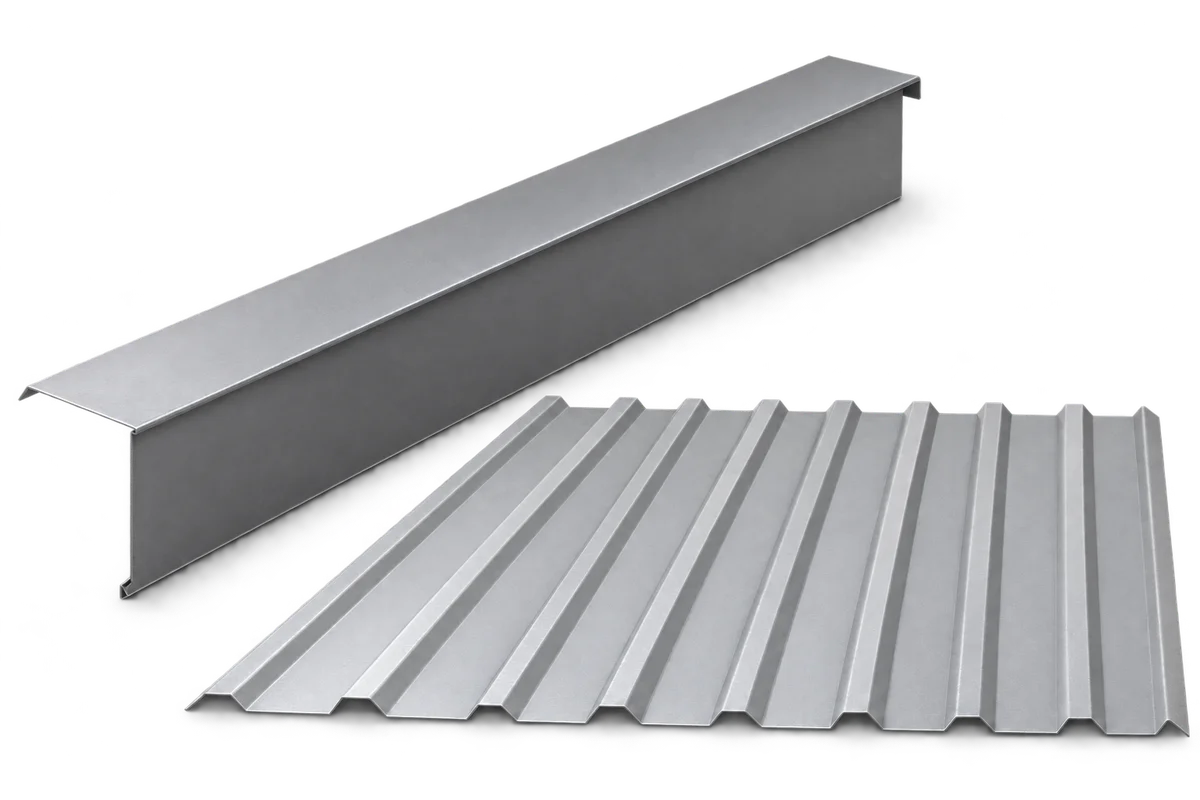
Verge flashing needs an end detail at both the eaves and the ridge. Components with different functions meet there, so selecting the flashing should not stop at the section of its straight length. The whole connection needs a solution suited to the particular covering and roof layers. This guide helps prepare a discussion with the roofer about end geometry, drainage direction, installation sequence and detail records. It does not give a universal overlap length or cutting pattern. Those particulars must come from the relevant instructions and design. The aim is to identify unresolved decisions before fabricated flashings reach the site and require alteration without a prepared solution.
Sketch the three adjoining components
Show the verge flashing, outer edge of the covering and the flashing adjoining its end. Add a side view if the plan does not explain heights. A roof outline alone can hide a clash caused by components at different levels.
Define the lower termination
At the eaves, establish where water running along the flashing will go and whether the termination suits the gutter arrangement. Covering a visible gap with metal is not enough. The lower section must work with the intended drainage route.
Also check the area beside the fascia and gable finish. Separately ordered flashings may have incompatible ends. Before fabrication, give the installer drawings of all adjoining pieces instead of agreeing each only with its individual supplier.
Do not copy a lower-end detail from a photograph of another house without comparing systems. Backing pieces, folds and connections may be hidden. A photograph can communicate the desired appearance but cannot replace a complete construction detail.
Check the approach to the ridge
At the upper end, establish how the verge flashing meets the ridge cap or other ridge detail. Different profile heights may need a different termination. Straight-section dimensions do not define cuts, closures or the way pieces cooperate at the corner.
Where ridge ventilation is part of the design, coordinate the verge closure with it. An additional cover must not unintentionally change the function of planned openings. Do not choose a seal solely because it can be pressed tightly into a space.
Review the layers beneath the metal
Ask for the membrane or other underlay termination to be shown in the detail drawing. Its position should follow the roof assembly. Concealing everything with metal does not demonstrate that water on the underlying layer has a suitable outlet.
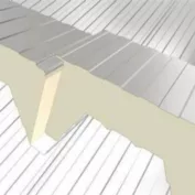
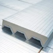
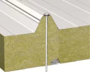
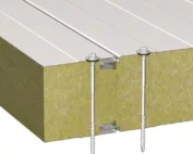
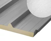
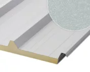
For a sandwich-panel roof, agree edge and core protection using the solution for that product. Do not assume the same underlying layers as for metal tiles on battens. A similar flashing name does not mean the entire roof detail is identical.
Agree the installation sequence
Before work begins, determine which pieces go in first and which close the joint. The installer needs access to the specified fixing positions. Agreeing the sequence only after fastening a cover can mean dismantling completed parts again.
Include end-fit assessment in the check of the first complete section. If a clash appears, resolve its cause before repeating the detail elsewhere. Adding more sealant alone does not resolve incorrectly selected geometry.
Inspect the complete connection
At acceptance, assess both ends and the length between them as one assembly. Look for unagreed openings, projecting edges and shape changes. Areas inaccessible from a safe position should be checked by a professional with suitable access.
Retain approved end drawings and photographs taken before concealment. For a later additional order, straight verge-flashing dimensions alone may not recreate the assembly. Connection records explain how the element was intended to work with the eaves and ridge.
7 branches. Materials closer to your project.