Installation and execution
Installing insulated roof panels: sequence of work and key details
In brief
A roof panel schedule needs to agree with both the structural drawings and the fitting instructions for the selected panel. Before delivery, check lengths, support positions, joint details and the direction in which the roof will be laid. Two PIR panels can both be 100 mm thick yet use different joints. Confirm the facing and core thicknesses and the requirements of the actual model. Check that the supports are in plane and that lifting will protect the edges. Once fitting starts, inspect the joints, fixings, seals and flashings as the work progresses.
What should be checked before delivery of the plasterboard?
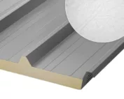
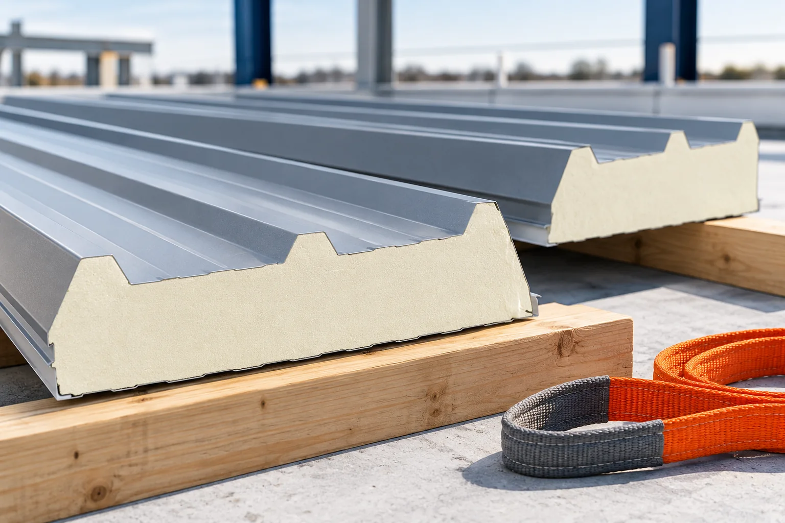
First, the structural design is compared with the material schedule. The panel lengths, support layout, installation direction and connection details are required. The thicknesses of the facings and core are also important. Two panels described as PIR 100 mm may have different joints, load-bearing parameters and installation requirements. They should not be substituted without assessing conformity with the design.
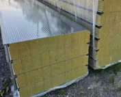
The unloading area must allow packs to be positioned safely and equipment to operate. Stacking rules differ between instructions, so the permissible number of packs should not be assumed in advance. The material must be protected from water accumulating between the facings. The storage cover must not turn the pack into a sealed container full of moisture. The deadline for removing the protective film should also be checked.
How to prepare the supports?
The purlins should lie in the correct plane and have a bearing width in accordance with the documentation. Unevenness can make it difficult to close the joint or introduce unforeseen stresses. Their spacing, connections and surface condition are checked. The panel is not intended to straighten poorly executed structure. Pulling it down with a large number of screws is not a correct way of removing level differences.
Before laying the material, the sealing elements specified at the supports and flashings must be prepared. Their arrangement should correspond to the details, not to the random availability of tape. Space for panel deflection and thermal movement is also important. The length of the elements and the dark colour of the facing can influence the behaviour of the roof. These limitations should be checked before the order is approved.
How to lift the panel onto the roof?
The lifting method is selected according to the length, weight and instructions for the material. The panel should retain its correct shape without point loading that crushes the edge. Vacuum lifters require appropriate preparation of the surface, including removal of the film at the gripping point if the instructions so specify. It must not be assumed that the transport film is a safe surface for lifting the entire element.
Weather has a direct influence on safety. A large panel acts as a surface that catches the wind, and precipitation makes work and sealing more difficult. Work is interrupted under conditions not permitted in the instructions and the safety plan. The wind speed limit given for one system is not universal approval for every device and panel size. Both sets of requirements must be taken into account.

How to connect and fasten the elements?
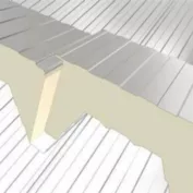
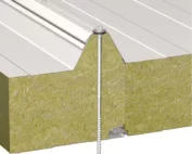
The first panel is positioned with its location checked relative to the eaves and the edge. An error at the beginning can accumulate in subsequent runs. The joints should connect correctly without damaging the protruding facings. Seals and sealants are placed where they are specified in the detail. Filling the entire joint with random foam does not replace the designed air and water seal.
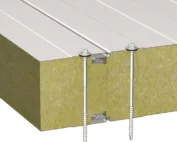
The type, length and number of fasteners depend on the substrate and the loads. Other requirements may apply at roof edges and corners. Tightening must not crush the facing or leave a loose washer. If panels are to be joined along their length, appropriate laps and support are needed. This is not done at any arbitrary point just to use up shorter elements.
How should openings and flashings be executed?
Service penetrations, rooflights and larger openings should be allowed for in the design. Cutting out a section of panel may change the way loads are transferred. The required reinforcements and frames are not an aesthetic addition. Tools approved by the instructions are used for cutting. An angle grinder damages the coatings, and swarf left on the roof can later create corrosion hot spots.
The ridge, eaves and side edges require matching flashings and closure of the exposed core. The direction of drainage and the method of sealing must be maintained. Water from the roof must reach the intended drainage. The cladding should not end above an incidental gap in the wall. Details where the roof meets the façade are resolved together, especially in a heated hall.
How should the completed roof be accepted?
Acceptance covers the joints, fastenings, flashings, penetrations and the condition of the surface. Swarf, waste and film are removed from the roof within the period specified for the product. The free flow of drainage and the places where moisture may have been trapped are checked. It is worth keeping photographs of the details before they are covered. They help establish how the work was carried out if a question about tightness arises later.
The rules for movement during servicing must also be established. A roof panel does not mean an unrestricted working surface for people and heavy equipment. Access routes and loads should be allowed for. Inspections after severe weather events and periodic cleaning make it possible to catch minor damage. Careful installation gives a good start, and proper handling maintains its results.
7 branches. Materials closer to your project.